Harsh environments expose weaknesses that remain hidden in ordinary workplaces. Dust enters cabinets, salt corrodes connectors, and vibration loosens critical fasteners. Extreme heat can reduce battery life and distort sensor readings. Cold conditions may stiffen seals and delay mechanical responses. In these settings, what makes a safety system effective in harsh environments is not one impressive feature. It is dependable performance across changing and combined hazards.
This guide examines seven safety system features designed for demanding conditions. These include rugged construction, environmental sealing, accurate detection, fail-safe operation, clear alarms, backup power, and simple maintenance. Each feature supports a practical goal: helping people identify danger and respond before a minor fault becomes a serious incident. Field experience shows that small details matter. A visible status light may prevent confusion during a noisy shift. A protected cable gland may stop moisture from reaching a control panel. A tested backup circuit may keep alarms active during a power interruption.
Reliable systems also require disciplined inspection and documented testing. Manufacturer specifications provide a starting point, but real operating conditions can be less predictable. A system rated for dust may still struggle with abrasive particles and repeated cleaning. That distinction deserves attention. No design is perfect. Sensors can drift, seals can age, and operators can misunderstand warnings. The strongest safety approach accepts these limits and builds regular verification into daily practice. The following features offer a clear framework for evaluating safety systems before harsh conditions reveal their weaknesses.
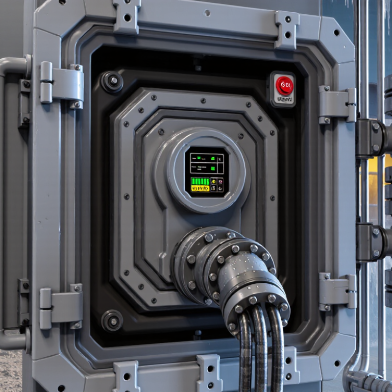
Harsh environments demand more than a rugged-looking enclosure. IEC 60529 IP66 indicates protection against dust and powerful water jets. IP69K adds resistance to high-temperature, high-pressure washdown. That difference matters near food-processing lines, outdoor pumps, and equipment cleaned with rotating spray heads. Water can enter through cable glands, damaged seals, or poorly closed doors. A test rating cannot compensate for careless installation.
NEMA 4X adds protection against water, dust, and corrosion. It is valuable in coastal facilities, chemical areas, and rooms with frequent sanitation. However, NEMA and IP classifications are not identical. Engineers should verify the test conditions, materials, drainage design, and maintenance schedule. ATEX assessment requires a separate review. Zone 0, 1, and 2 describe gas risks, while Zones 20, 21, and 22 address combustible dust. The correct equipment depends on the zone, substance, temperature class, and ignition protection method. An IP rating alone does not make equipment suitable for an ATEX zone.
Tips: Match the enclosure to the actual cleaning method. Inspect seals after every panel opening. Keep cable entries facing downward where practical. Record corrosion, cracking, and loose fasteners during inspections. I have seen strong enclosures fail because a small gland was ignored. That mistake is easy to repeat. Safety reviews should question assumptions, not just confirm paperwork.
| No. | Safety System Feature | Primary Hazard Addressed | Relevant Risk Classification or Requirement | Recommended Design Control | Verification and Maintenance |
|---|---|---|---|---|---|
| 1 | Sealed, Washdown-Resistant Enclosure | Water ingress, dust contamination, cleaning chemicals, and corrosion caused by frequent washdown. |
IEC 60529 IP66 Dust-tight and protected against powerful water jets. IP69K High-temperature, high-pressure washdown protection; the test basis should be confirmed because IP69K is commonly specified under ISO 20653, while IEC 60529 includes the IPX9 water test. |
Use sealed cable entries, protected connectors, hygienic enclosure geometry, corrosion-resistant fasteners, and gaskets compatible with the operating temperature and cleaning agents. | Inspect seals, cable glands, door compression, and drain paths. Repeat ingress testing after enclosure modification, repair, or gasket replacement. |
| 2 | Corrosion-Resistant Construction | Loss of structural integrity, electrical faults, and seal failure caused by salt spray, humidity, process chemicals, or abrasive deposits. |
NEMA 4X Enclosure classification for indoor or outdoor use with protection against windblown dust and rain, splashing or hose-directed water, and additional corrosion resistance. NEMA ratings are not direct equivalents to IEC IP ratings. |
Select suitable stainless steel, coated metal, or engineered polymer materials. Separate dissimilar metals where galvanic corrosion is possible and specify chemical compatibility for the complete assembly. | Check for coating damage, pitting, galvanic attack, and fastener degradation. Confirm that replacement parts retain the required corrosion and enclosure performance. |
| 3 | Hazardous-Area Equipment and Wiring | Ignition of flammable gas, vapor, mist, or combustible dust released during normal operation or an abnormal event. |
ATEX Gas Zones Zone 0: explosive gas atmosphere present continuously, for long periods, or frequently. Zone 1: likely to occur occasionally in normal operation. Zone 2: not likely in normal operation, and if it occurs, it exists only for a short period. ATEX Dust Zones Zone 20, Zone 21, and Zone 22 use the equivalent continuity categories for combustible dust atmospheres. |
Match equipment category, protection concept, gas or dust group, temperature class or maximum surface temperature, ambient range, and installation method to the area classification. | Verify the equipment marking, certificate, installation documents, cable glands, barriers, bonding, and inspection schedule. Do not treat an IP rating alone as proof of ATEX suitability. |
| 4 | Emergency Stop and Safe-State Shutdown | Entanglement, crushing, unexpected movement, thermal escalation, or continued energy release during an emergency. | Apply a risk-assessment-based safety function. Emergency-stop devices should be readily accessible, manually reset, and designed so that resetting does not automatically restart hazardous motion. | Use a safety-rated stop circuit or safety controller appropriate to the required risk reduction. Remove or control relevant electrical, pneumatic, hydraulic, thermal, or stored energy. | Perform functional tests at defined intervals. Confirm actuator accessibility, reset behavior, stop response, diagnostic indication, and protection against unintended restart. |
| 5 | Guarding and Interlocked Access Panels | Contact with moving parts, energized components, hot surfaces, pressurized systems, or hazardous process materials during access. | Use fixed guards or interlocked guards according to the assessed risk. In hazardous areas, the switch, actuator, enclosure, and wiring must also be suitable for the applicable ATEX zone. | Use monitored guard switches, coded actuators, trapped-key systems, or equivalent controls where bypass or frequent access presents a risk. Design for safe access and controlled dissipation of stored energy. | Inspect guard alignment, fastening, tamper resistance, interlock operation, and stopping performance. Record bypasses and corrective actions. |
| 6 | Temperature, Gas, and Dust Monitoring | Overheating, fire, explosion, oxygen deficiency, toxic exposure, and hazardous accumulation of combustible gas or dust. | Alarm and shutdown thresholds must be determined from the process risk assessment, material properties, ventilation design, and applicable occupational and hazardous-area requirements. | Provide independent sensors where a single failure could create unacceptable risk. Use high-temperature alarms, gas detection, differential-pressure monitoring, dust concentration monitoring, and automatic isolation or shutdown where justified. | Calibrate sensors according to manufacturer and site procedures. Test alarms, voting logic, detector coverage, ventilation interlocks, and fail-safe behavior; document calibration and bump-test results. |
| 7 | Fail-Safe Diagnostics and Preventive Maintenance | Undetected loss of protection caused by sensor failure, power interruption, wiring damage, blocked ventilation, degraded seals, or unauthorized configuration changes. | Safety functions should be evaluated for required reliability and diagnostic coverage. Environmental ratings such as IP66, IP69K, or NEMA 4X describe enclosure protection; they do not replace functional safety or maintenance requirements. | Use monitored power supplies, short-circuit and open-circuit diagnostics, watchdogs, clearly defined safe states, protected configuration access, and a documented inspection and proof-test plan. | Test diagnostic annunciation, backup power where provided, communication loss behavior, shutdown outputs, enclosure condition, earthing or bonding, and safety records at planned intervals. |
It should tolerate dust, vibration, moisture, heat, and temperature changes. Rugged enclosures alone are not enough. Wiring matters too.
SIL describes the required reduction of dangerous risk for a safety function. SIL 3 generally requires stronger risk reduction than SIL 2. Engineers must verify PFH or PFDavg for the operating mode.
Diagnostics should identify open circuits, short circuits, stuck signals, memory faults, and communication loss. They should also detect inconsistent dual-channel inputs. A silent fault is dangerous.
Dual-channel circuits provide independent signal paths for comparison. Fault monitoring can expose failed contacts, wiring shorts, or inconsistent channels. A single contact may fail silently.
An independent watchdog should detect the freeze. It should move the process toward a defined safe state. That response must be tested.
Emergency stops should remain visible, reachable, and mechanically reliable. Guard interlocks should confirm door position reliably. Emergency stops do not replace guarded access protection.
Proof tests reveal faults that automatic diagnostics may miss, including loose terminals and intermittent wiring. Teams should test realistic conditions. Clean drawings can hide weak installations.
Test every guard, emergency stop, manual reset, channel fault, and final response. Repeat checks after vibration, cleaning, maintenance, and production changes. Field wiring deserves uncomfortable attention.
A monitored manual reset should be required after an interlock opens. The machine must not restart automatically. This detail is easy to underestimate.
Record hazard analysis, SIL or performance-level calculations, sensor response times, final-element behavior, proof-test intervals, and site records. Use independent review. Assumptions can mislead.
What makes a safety system effective in harsh environments is its ability to maintain reliable protection despite water, dust, chemicals, temperature extremes, vibration, and hazardous atmospheres. A strong design begins with risk classification, using protection levels such as IEC 60529 IP66/IP69K, NEMA 4X, and appropriate ATEX zone requirements. Physical protection should include durable sealing, corrosion-resistant materials, and dependable operation at temperatures as low as −40°C. These features help prevent environmental conditions from reducing system performance or creating additional hazards.
Functional safety is equally important. IEC 61508 SIL 2 or SIL 3 logic, combined with fail-safe diagnostics, can detect faults and move the system to a safer state. Machine protection should include ISO 13849 PL d or PL e interlocks and emergency stops. System resilience is strengthened through redundant power, IECEx certification where required, and IEC 60068 environmental testing. Together, these measures create a safety solution that remains dependable, diagnosable, and protective throughout demanding industrial operations.

 Agonex Safety